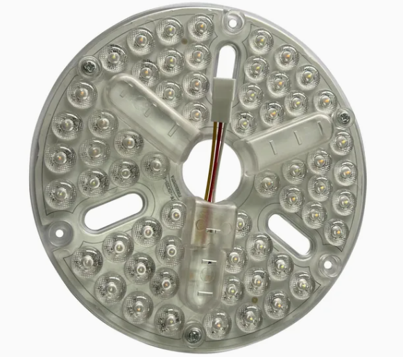
24W Ceiling LED Light Module
24W ceiling LED light module listing. Confirm the light source, external driver, dimming interface and mechanical fit for the project.
Built for your product platform.
24W Ceiling LED Light Module: recorded scope
24W ceiling LED light module listing. Confirm the light source, external driver, dimming interface and mechanical fit for the project. This page records what the listing currently states and separates it from what still has to be confirmed for your project. It is a working reference for an enquiry, not a released specification: the approved drawing revision, motor data and test plan take precedence over anything shown here.
What this listing records
| Listing title | 24W Ceiling LED Light Module |
|---|---|
| Product category | LED Lighting Modules |
| Internal reference | SK-244 |
| Power figure in title | 24 W (confirm rated conditions) |
| Signals named in title | LED |
| Configuration status | Not yet confirmed for a specific project |
Figures taken from a listing title are descriptive. They indicate the intended application; they do not establish the rated conditions of the unit supplied for your programme. Confirm them against the approved project configuration before quoting, sampling or designing around them.
Mechanical and thermal fit of a module
A lighting or control module is constrained by the space it occupies and the heat it has to shed. Fit and thermal behaviour are decided by the host product, so the module brief has to include the cavity dimensions, the airflow available and the mounting orientation before a sample is meaningful.
- Cavity dimensions and fixing method in the host product
- Available thermal path and expected ambient in operation
- Electrical interface, connector type and lead length
- Optical or functional performance the host product must achieve
What to confirm before sampling
These are the inputs the engineering team needs in order to turn this listing into a reviewable specification for led lighting modules.
- Light source, drive current and thermal design limits
- Dimming interface and compatibility with the chosen controller
- Mechanical fit, connector and installation method
- Target-market photometric and safety documentation
Why this page does not quote full specifications
Publishing a numeric table that has not been traced to an approved drawing is worse than publishing none: a buyer can design a housing, a harness or a certification plan around a figure that was never verified. The parameters that decide whether this part fits your product – rated current under your load, thermal margin in your enclosure, connector pinout on your board revision, and the compliance scope for your market – are only meaningful once they are tied to a specific configuration.
What that means in practice is that the review is driven by your inputs rather than by a published table. Send the motor or load data, the available drawings and the target market, and the engineering team can respond with the specific values that apply to your build, together with the measurement conditions behind them. Where a figure cannot be supported for your configuration, the honest answer is to say so and propose the test that would establish it.
The figures named in this listing (24 W) describe the intended application class. Treat them as a starting point for the conversation, and confirm the rated conditions – input, load, duty cycle and ambient – before they are used in a design decision or a quotation.
Application notes for this listing
Lighting integration
Where a controller carries a lighting load, the lamp and its driver are part of the control problem. Dimming method, minimum load and behaviour at the bottom of the dimming range all depend on the lamp electronics rather than on the controller alone.
- Lamp type and driver topology
- Dimming method and minimum load
- Leakage limit with the light switched off
Light output and thermal life are decided together
A lighting module is limited as much by heat as by drive current. Junction temperature determines both output and service life, and it depends on the host fixture as much as on the module. Photometric figures quoted without the thermal condition they were measured at are difficult to compare between suppliers.
- State the fixture cavity and the available thermal path
- Confirm the drive current and the resulting junction temperature
- Agree the dimming interface and its compatibility
- Confirm which photometric and safety documents the market requires
Where this type of part usually goes wrong
Modules fail on thermal margin and mechanical fit. A module that meets its output target on an open bench can underperform once it is enclosed, and a few millimetres of clearance can decide whether the assembly goes together at all.
Validate in the fixture, not on the bench
Measure output and thermal behaviour with the module installed in the host product, at the ambient the product will see. A bench measurement in free air describes a different thermal situation from the enclosed one, and the enclosed result is the one that determines service life.
Keep the drive current, the measured junction or case temperature, the fixture conditions and the photometric result together. A change to the fixture, the thermal path or the drive current invalidates the earlier measurement and should be repeated.
Frequently asked questions.
Can this product be customized for our application?
Yes. Sankey can match the controller hardware, firmware, interfaces, protection functions, and production test plan to your motor and target market.
What information is needed for a project quotation?
Please share motor data, input voltage, rated power, required functions, target certifications, product drawings where available, and expected annual volume.
How is production quality validated?
Production support can include incoming inspection, AOI, ICT, functional testing, aging, and reliability checks appropriate to the confirmed project specification.
